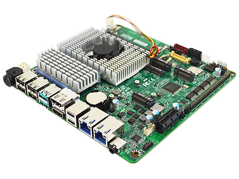
- Intel® Core™ i5-1335UE Processor, 13th Gen Raptor Lake-P
- Long-Life Embedded Class with Planned Lifecycle Through Q1'2038
- 2 * M.2 M-key for SSD, 4 * USB 3.2 Gen2, PCIe 3.0 x1
- 2 * Intel 2.5GbE, 1 * M.2 B-key, 1 * M.2 E-key, 6 * Serial
- Supports 4 Displays, 2 * HDMI, 2 * USB-C (DP), eDP/LVDS
- 2 * DDR5-4400 Dual Channel SODIMM up to 64GB
- Supports BIOS Recovery, ECO-design for EuP/ErP

Specification
Model SeriesMI24
Part NumberMI24-133E0 (i5-1335UE)MI24-133E2 (i5-1335UE, Onboard TPM 2.0)
Form FactorMini ITX (170 x 170mm)
ProcessorIntel® Core™ i5-1335UE Processor, 13th Gen Raptor Lake-P, vPro Essentials (Max Assured Power 28W)
Memory2 x Dual Channel Non-ECC DDR5-4400 SODIMM up to 64GB
GraphicsIntel® Iris® Xe Graphics eligible
AudioRealtek ALC888S HD Audio and 3W Amplifier
LAN1 x Intel I225-V 2.5GbE
1 x Intel I225-LM PCIe 2.5GbE
Storage1 x SATA3 6Gb/s
1 x M.2 2242/2280 (PCIe 4.0 x4 NVMe, M-key)
1 x M.2 2242 (SATA, M-key)
Super IOFINTEK F81966D
TPMIntel fTPM 2.0 (PTT) Trusted Computing FirmwareIntel fTPM 2.0 (PTT) Trusted Computing Firmware
Onboard NUVOTON TPM v2.0
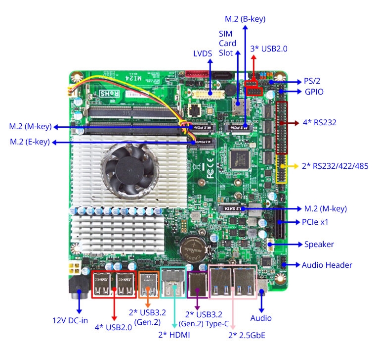
Back Panel Connectors
1 12V ~ 24V DC-in Jack (4-pin Mini-DIN)
4 USB 2.0
2 USB 3.2 Gen 2 (10 Gb/s)
2 HDMI 2.0b (4096 x 2304 @ 60Hz)
2 USB 3.2 Gen 2 Type-C, DP ALT Mode, PD 5V/3A
2 RJ45 2.5GbE LAN (10/100/1000/2500)
1 3.5mm Line-out/MIC-in Jack

Onboard I/O Connectors
1 PCIe 3.0 x1 Slot
1 SATA3 6Gb/s Connector
1 M.2 M-Key, 2242/2280 (PCIe 4.0 x4 NVMe)
1 M.2 M-Key, 2242 (SATA)
1 M.2 E-key, 2230 (USB2.0 and PCIe 3.0 x1 CNVi WiFi)
1 M.2 B-key, 3042 3052 (USB3.2/2.0 and PCIe 3.0 x1 for Cellular)
2 USB Headers for 3 additional USB 2.0 Ports
6 Serial Headers (4 * RS232, 2 * RS232/422/485)
1 24-bits Dual Channel LVDS/eDP (1920x1200 @60Hz)
1 Nano SIM Socket
1 8 bit GPIO Header
1 PS2 Keyboard/Mouse Header
1 AT/ATX Mode Jumper
1 9-pin Front Audio Header
1 5-pin SMBUS Header
1 Fan Header
1 4-pin Alternate Power-in Connector
Power Supply for MI24
External Power Supply – the board can be powered with a +12V ~ +24V external power supply though a DC connector on the back panel. The rear +12V ~ +24V DC jack accepts plugs with a 4-pin Mini-DIN connector.

Internal Power Supply – the board can alternatively be powered via the internal +12V ~ +24V DC 2 x 2 power connector, where pins 1 and 2 are +12V ~ +24V (±5%) DC and pins 3 and 4 are GND. The connector used is Molex Micro-Fit (3mm pitch), right-angled, 4-pos/dual row (2x2).

Caution: There is no isolation circuitry between the external +12V ~ +24V DC jack and the internal 2 x 2 power connector. It is the system integrator's responsibility to ensure no more than one power supply unit is or can be attached to the board at any time and to ensure the external +12V ~ +24V DC jack is covered if the internal 2 x 2 power connector is to be used.
Market Segments Supported
√ Edge Computing
√ Digital Signage
√ Industrial PCs
√ Factory Automation
√ Public Sector
√ Digital Security
√ Surveillance Application
Environment
Operating Temperature : 0 ~ 60°C (with 0.7m/s air flow)
Storage Temperature : -20 ~ 85°C
Humidity: 10% ~ 90% RH @40°C (non-condensing)
Features

Ordering Info
Part Number Description
MI24-133E0 i5-1335UE Mini-ITX motherboard
MI24-133E2 i5-1335UE Mini-ITX motherboard with onboard TPM 2.0
MI24-13350 i5-1335U Mini-ITX motherboard
MI24-13352 i5-1335U Mini-ITX motherboard with onboard TPM 2.0
F04-MB-101-F (Incl) IO shield
G01-SATA3-BL-1F (Incl) SATA data cable
G01-PW4PS2S-322-1F (Incl) SATA power cable
G01-COM-H2M22-1F (Incl) COM cable
OS Support List
Windows Linux
Windows 10 64bit CentOS 9
Win 10 IoT Enterprise 64-bit Debian 11.4
Windows 11 64bit Fedora 36-1.5
Win 11 IoT Enterprise 64-bit OpenSUSE 15.4
Ubuntu 22.04
pfSense 2.6.0
OpenBSD 7.1
Downloads
MI24-133E0/13350 BIOS A03 (Default Intel PTT) Release Date 2023-11-24
Description Update DRAM Options.
Download  FAITYA03.ZIP for UEFI (BIOS Recovery *.RY file included)
Flash Instructions for UEFI 1. Unzip the file and copy to the USB flash drive with FAT32 format.
2. Insert the USB drive, Enter BIOS, and select "Built-in EFI Shell" from Boot Override.
3. Type "fs0:" to change path when you see Shell prompt. Might be "fs1:" if you have more than one drive.
4. Type *.NSH to auto update BIOS.
5. Power off the system after the update finished.
* Read Detailed Instructions in PDF
Revised History [A02]. Update DRAM Compatibility.
[A01]. Initial BIOS.
MI24-133E2/13352 BIOS A03 (Default dTPM) Release Date 2023-10-26
Description Remove DRAM Option.
Download  BAITYA03.ZIP for UEFI (BIOS Recovery *.RY file included)
Flash Instructions for UEFI 1. Unzip the file and copy to the USB flash drive with FAT32 format.
2. Insert the USB drive, Enter BIOS, and select "Built-in EFI Shell" from Boot Override.
3. Type "fs0:" to change path when you see Shell prompt. Might be "fs1:" if you have more than one drive.
4. Type *.NSH to auto update BIOS.
5. Power off the system after the update finished.
* Read Detailed Instructions in PDF
Revised History [A02]. Update DRAM Compatibility.
[A01]. Initial BIOS.

· Please do not flash the BIOS UNLESS your system has a BIOS-related issue. Flashing the wrong BIOS can cause irreparable damage to the system.
· Please be aware that by flashing this BIOS you agree that in the event of a BIOS flash failure, you must contact your dealer for a BIOS replacement. There are no exceptions to this policy. Jetway does not have a policy of replacing BIOS chips directly with end users.


Drivers for MI24
  Windows 10 (64 bit) Windows 11 (64 bit)
Chipset  inf_rpl.zip  inf_rpl-p.zip
Graphic  gfx_rpl.zip  gfx_rpl-p.zip
Sound  audio_dch_rpl.zip  audio_rpl-p.zip
LAN  intellan_rpl.zip  intellan_rpl-p.zip
RST  rst_rpl.zip  rst_rpl-p.zip
ME  ime_rpl.zip  ime_rpl-p.zip
Manual
1.0  G03-MI24-F.pdf
Resources
FCC  FCC
CE  CE
LVD  LVD
RoHS  RoHS
Power Consumption Report  Reports available upon request
Temperature Test Report  Reports available upon request
Watchdog/GPIO sample code  Watchdog and GPIO sample code for Windows and Linux